
Simulink Tutorial Series – 11

In this article, I am going to explain you how to design the Edge detector functionality in Simulink.
I will build the Simulink models for Edge detector function step-by-step.
Matlab/Simulink is the leading software for model based development in aerospace, automotive industry etc.
There are several other online resources, where you can get theoretical knowledge about Matlab/Simulink. In fact, Matlab has very good documentation for each of their products. But, there are not many resources to explain the theory along with good working examples. This is going to be a series of articles. This is the 11th article in this series.
In every article in this Simulink Tutorial Series, I will add real-life working examples and show how to build models for a particular problem.
Problem Statement
Here is the Problem statement –
Design the Edge Detector function in Simulink to detect the rising edge of the signal.
Design the Edge Detector function in Simulink to detect the falling edge of the signal.
Note: This is also a popular interview question for Matlab/Simulink.
Assumption
I am assuming, you have already gone through my previous articles.
In one of these articles, I have explained the delay block in Simulink Library. Understanding the delay block is crucial to implement the up-down counter in Simulink.
Design the Rising Edge Detector function in Simulink
The edge detector function is a crucial concept for safety critical embedded application.
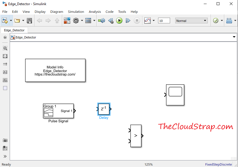
To design the Edge Detector function, I need the following Library Blocks:
- A pulse signal as an input
- Delay block
- Relational Operator block
- Display block
If you have gone through my previous posts, you already know how to find these blocks in the Simulink Library Browser.
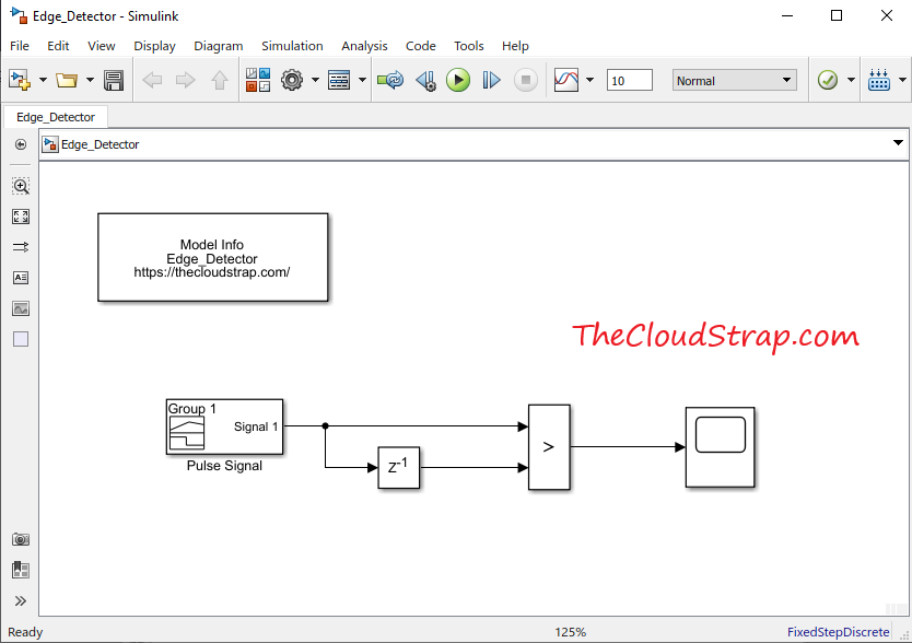
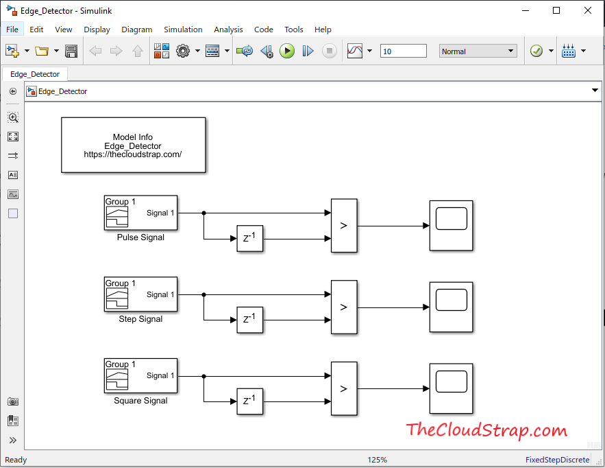
Now, I will just get these blocks from the Simulink Library browser and put them in a blank Simulink model/canvas.
I will join them up accordingly to implement the Rising edge detector function.
As you can see below, I have used to relational operator block. The relational block is used here to find out if the current input signal is greater than the previous cycle value. I can easily get the previous cycle value using the delay block.
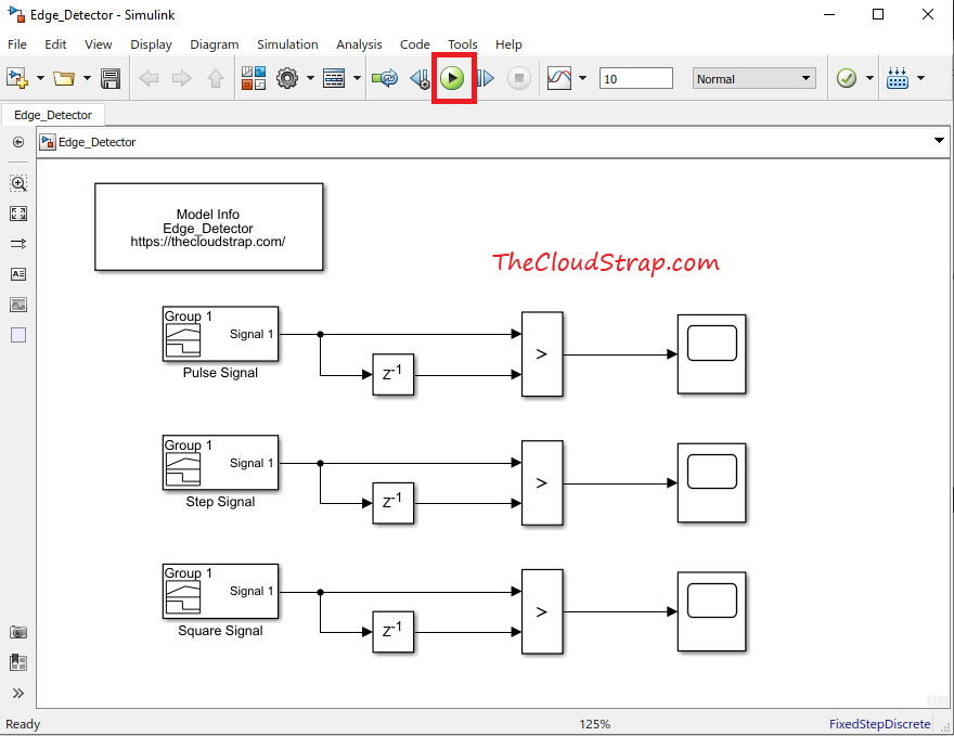
Now, I have completed adding all the required blocks to implement the functionality. I will now connect them up accordingly. I have also added a Model info block to display the block name in the top left corner of the model.
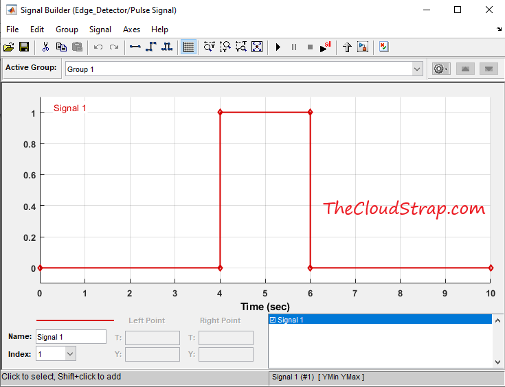
Now, let us ensure to set the input signal correctly. I will now, double click on the Pulse Signal block and make sure that the input signal pattern is correct.
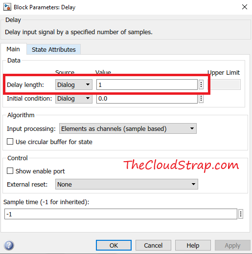
Now, I have to configure the delay block parameters. I will now double click on the delay block to open the block parameters window as shown below. The delay length parameter need to set to 1 since we just need one-cycle old data. The initial condition is set to 0.0. You can leave the other parameters to their default values.
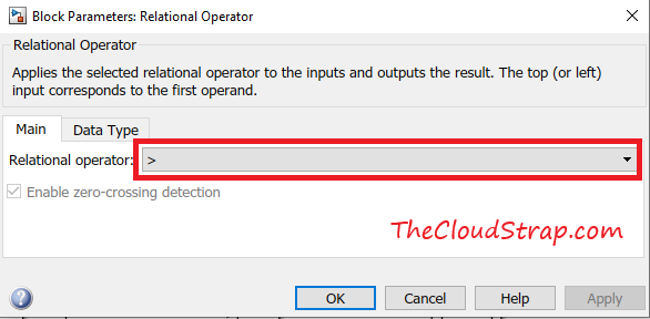
I also have to ensure the relational operator is set to the correct value. I will double click on the relational operator and select the relational operator as “>” i.e. “greater than”.
Now, let’s replicate the same for other input signals. For example, we want to test our model for Pulse Signal, Step Signal and Square Signal.
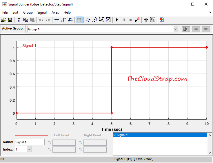
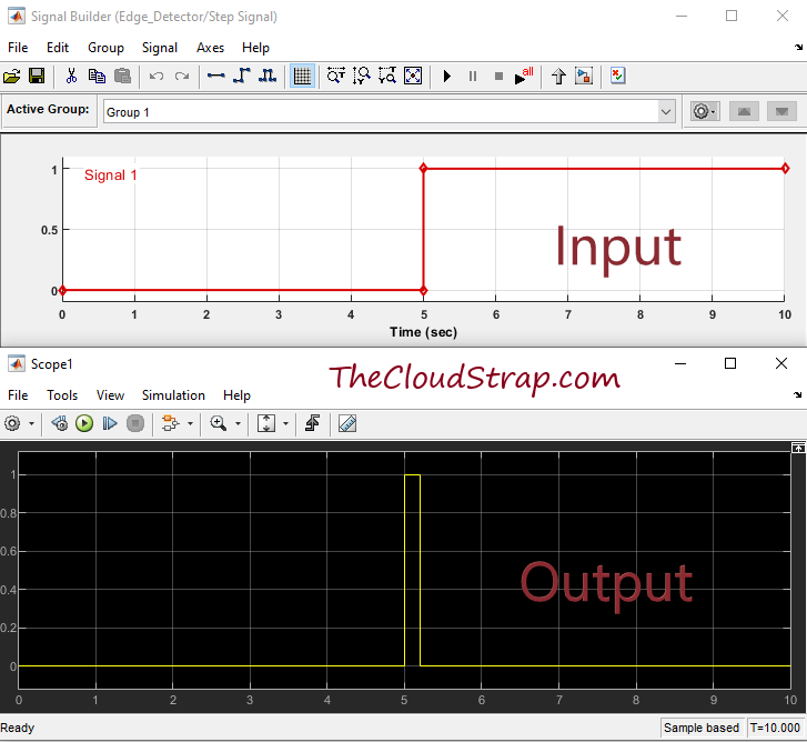
This is how the step signal looks like:
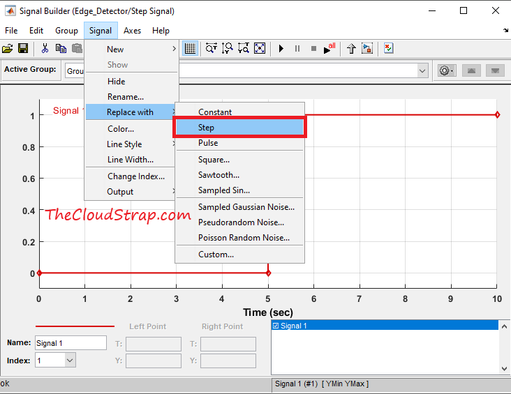
To replace the existing signal with a step signal, you need to double click on the Simulink block. The signal Builder window should open up as shown below.
Signal -> Replace With -> Step
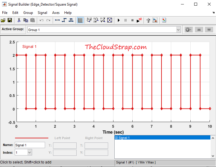
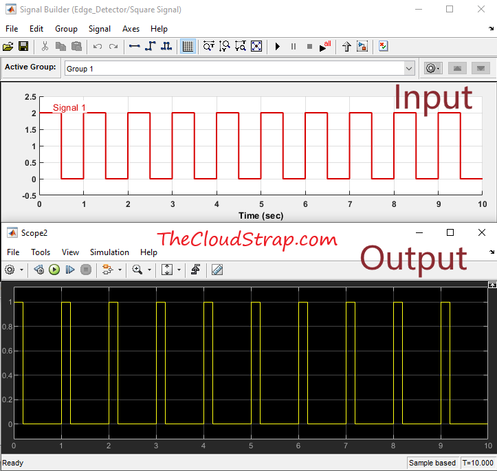
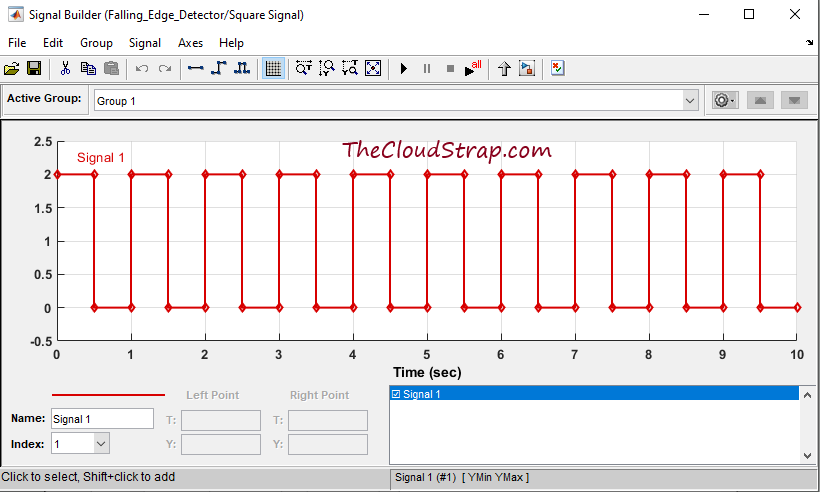
In the 3rd instance, I want to test if the model is working fine for the Square input signal. The Square input signal looks like this:
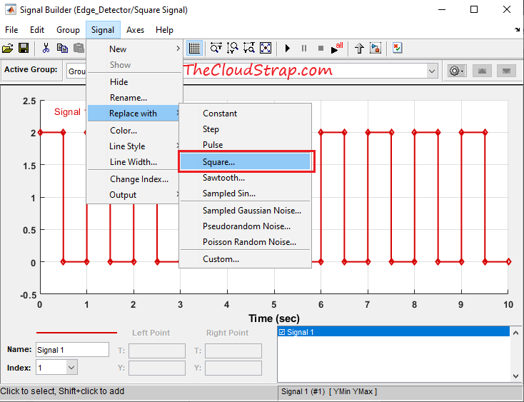
To replace the existing signal with a step signal, you need to double click on the Simulink block. The signal Builder window should open up as shown below.
Signal -> Replace With -> Square
Now, we have finished our model. Let’s now execute the Simulink model by hitting the green play button as shown below:
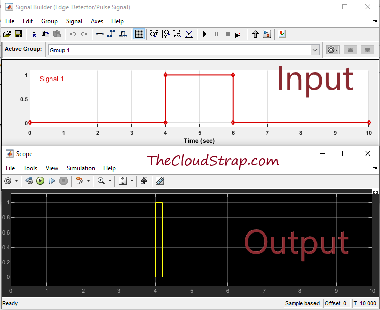
Here is the output for the Pulse signal. If you see the below output carefully, there is a rising edge at 4 sec. The scope output shows that the model detected this rising edge and set the output signal to True.
Here is the output for the Step signal. If you see the below output carefully, there is a rising edge at 5 sec. The scope output shows that the model detected this rising edge and set the output signal to True at 5 sec.
Here is the output for the Square signal. If you see the below output carefully, there are several rising edges i.e. at 1, 2, 3, 4 sec etc. The scope output shows that the model detected each rising edge and set the output signal to True at 1, 2, 3, 4 sec etc.
Design the Falling Edge Detector function in Simulink
So far, we have developed the Simulink model for rising edge detector function. Let us now develop the model for falling edge detector function.
The concept and model would very similar to rising edge detector function.
To model the falling edge detector function, I need to apply the following logic – “Check if the current signal value is less than the previous cycle value.” So, clearly, I just need to change the relational operator as “<” i.e. “less than” in this case.
So, here is our model for falling edge detector function:
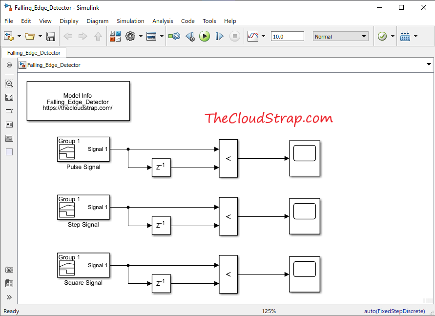
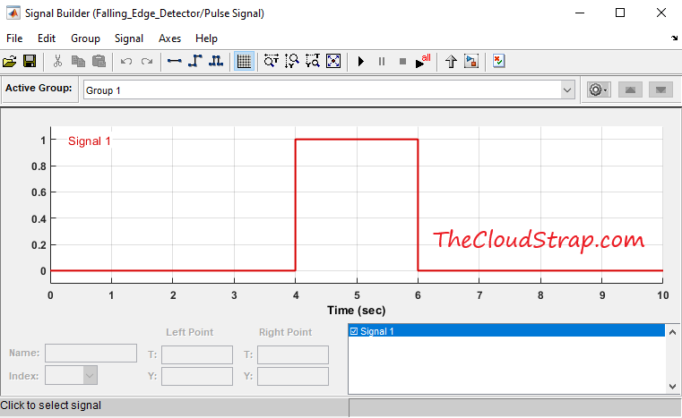
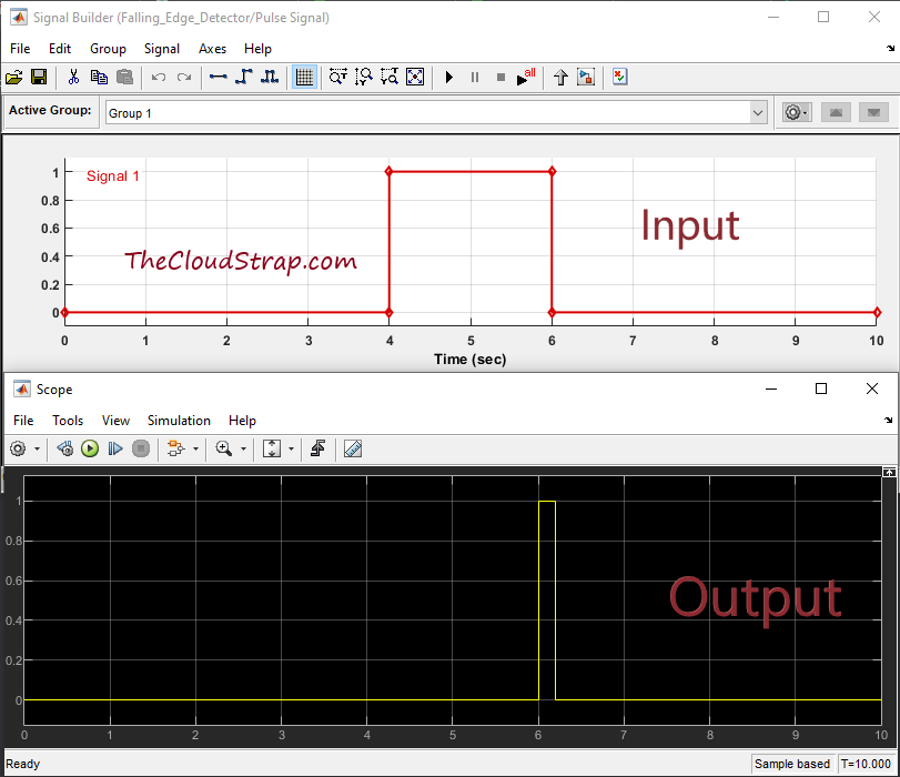
The first instance is for testing the Pulse signal:
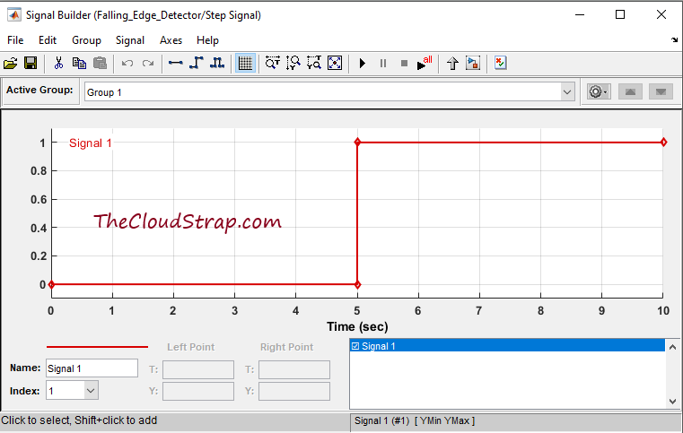
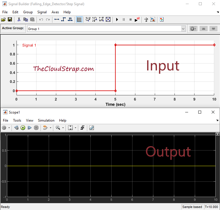
In the 2nd instance, we will test our model for Step signal:
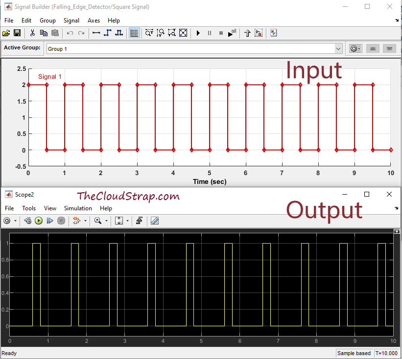
Lastly, in the 3rd instance, I will use the Square input signal:
Now, we have finished our model. Let’s now execute the Simulink model by hitting the green play button. Let us now focus on the Input and Output together to understand if the model is working correctly.
This is the input and output for the first instance i.e. for Pulse Signal. As you can see below, there is a falling edge at the 6 sec in the input. The output is set to True at 6 sec. So, clearly the model is working fine for the pulse signal.
Now, let us see the output in case of Step signal. In this case, there is only one rising edge at 5 sec. But, there is no falling edge.
Therefore, as you can see below the output is set to False always.
Here is the output for the Square signal. If you see the below output carefully, there are several falling edges i.e. at 0.5, 1.5, 2.5, 3.5 sec etc. The scope output shows that the model detected each falling edge and set the output signal to True at 0.5, 1.5, 2.5, 3.5 sec etc.
So, clearly, the model we have developed is working for all three types of input signals – Pulse signal, Step signal, Square signal.
Download Sample Model
You can download the Sample Model by Clicking HERE.
Summary
Matlab/Simulink is a well known and very popular tool used for Model Based Software Development in the aerospace and automotive industry.
Today, in this article (Simulink Tutorial Series – 9), I have explained step-by-step, how to calculate the Min/Max of a given input vector in the Simulink model using Simulink library blocks from scratch.
If you have any questions, please feel free to comment in the comment box below. 👇👇👇
I will keep sharing useful real-life Simulink model example here – Simulink Tutorial Series.
Happy learning!

This post was published by Admin.
Email: admin@TheCloudStrap.Com