
Simulink Tutorial Series – 3

Are you new to the world of Model-Based Development using Matlab/Simulink? Are you looking for a good working Simulink model examples / Simulink Tutorial to understand how Model-Based Development works?
If yes, then you are on the right page!
In this article, I am going to discuss exactly, what you are looking for.
Matlab/Simulink is the leading software for model based development in aerospace, automotive industry etc.
There are several other online resources, where you can get theoretical knowledge about Matlab/Simulink. In fact, Matlab has very good documentation for each of their products. But, there are not many resources to explain the theory along with good examples. This is going to be a series of articles. This is the 3rd article in this series.
In every article in this Simulink Tutorial Series, I will add real-life working examples and show how to build models for a particular problem.
What Will You Learn
In this article, I am going to explain to you how you can implement “switch-case” in the Simulink model.
If you are familiar with other programming languages such as C, C++, Java, or any other programming languages, you already know that every programming language has a “switch-case” construct.
Similarly, In Simulink, we can build a model including “switch-case” logic.
So, if you go through this article, you will be able to build your own Simulink model using “switch-case” logic.
Assumption
I am assuming, you already gone through my previous article – Simulink Tutorial – Series I and Simulink Tutorial – Series 2.
I have explained basic understanding of Simulink and “if-else” logic implementation in Simulink.
What You already know
From my previous posts, you already know –
- How to start Matlab
- How to open the Simulink from Matlab
- How to open a Blank Simulink Model
- How to open Simulink Library Browser
- How to find a block in Simulink Library Browser
- How to implement if-else logic in Simulink Model
I have discussed all the above points in my previous post.
What is Switch-Case Logic
Most of you may have previous coding background and understand the switch-case construct. If you already know it, you can skip this section and move to the next bullet point.
Switch-Case allows the programmer to take decision based on multiple condition. Here is an example of switch-case in c programming language:
switch (weekday) {
            case 1:
                printf("Monday");
                break;
            case 2:
                printf("Tuesday");
                break;
            case 3:
                printf("Wednesday");
                break;
            case 4:
                printf("Thursday");
                break;
            case 5:
                printf("Friday");
                break;
            case 6:
                printf("Saturday");
                break;
            case 7:
                printf("Sunday");
                break;
            default:
                printf("Out of range value");
                break;
        }
Here in the above example, based on the value of weekday, the corresponding case will be executed. For example, if the weekday is set to value 4, the printf statement under the case-4 will be executed, and “Thursday” will be printed.
Simulink Blocks for Switch-Case
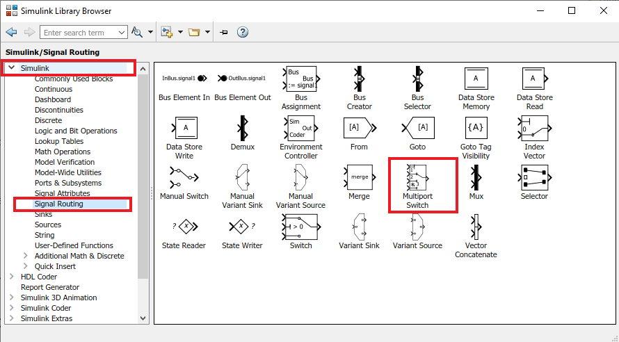
The switch-case logic can be easily implemented in Simulink model using multiport switch block. The multiport switch block can be found under the “Signal Routing” section in Simulink Library Browser.
The other Simulink blocks that I will using to demonstrate this example are:
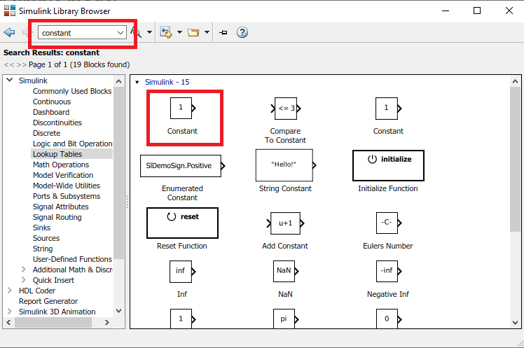
- Constant Block
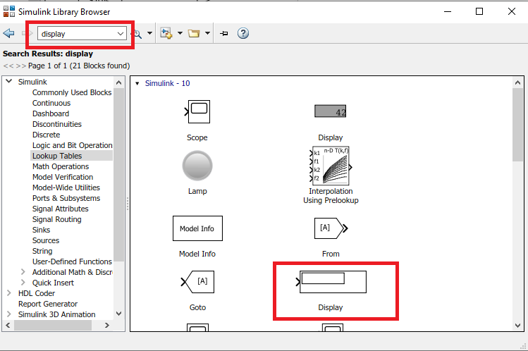
- Display Block
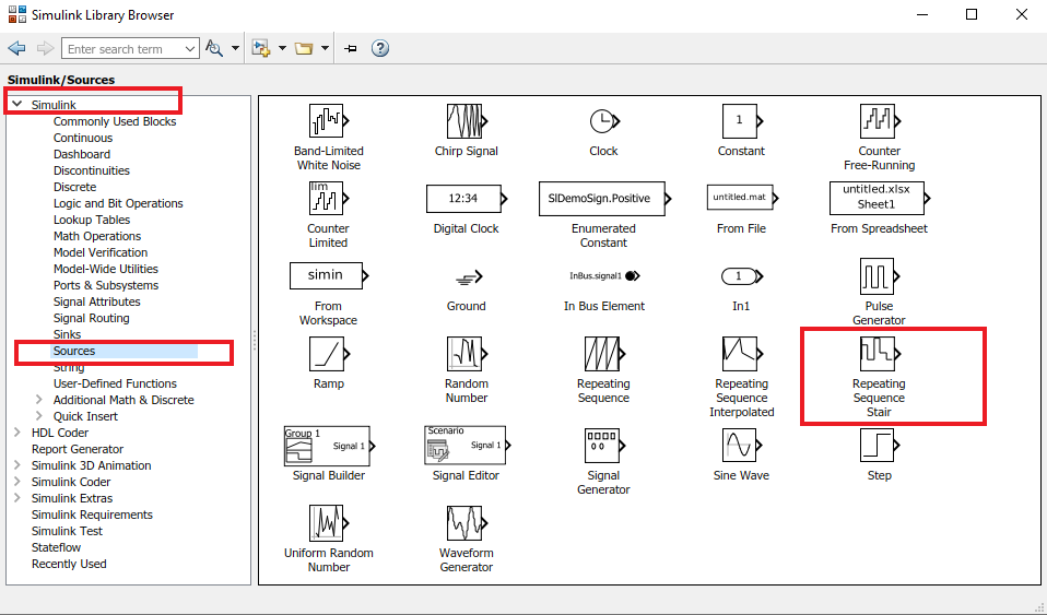
- Repeating Sequence Stair Block
- Scope Block
Simulink Library Block – Multiport Switch
Now, I will open the Simulink Library Browser and find the required Simulink blocks. I will drag and drop them in the empty Simulink Model canvas.
In my previous post, I have explained how to find a particular block in the Simulink Library Browser.
So, let me just open Simulink Library browser and drag and drop the Multiport Switch.
Simulink -> Signal Routing -> Multiport Switch
Simulink Library Block – Constant
Similar way, now I will get the constant block and drag and drop in my blank Simulink Model canvas.
Simulink -> Sources -> Constant
Simulink Library Block – Repeating Sequence Stair
This block (Repeating Sequence Stair) will help us to provide the input to the multiport switch block.
Simulink -> Sources -> Repeating Sequence Stair
Simulink Library Block – Display
The display block will help you to see the output of the multiport switch block.
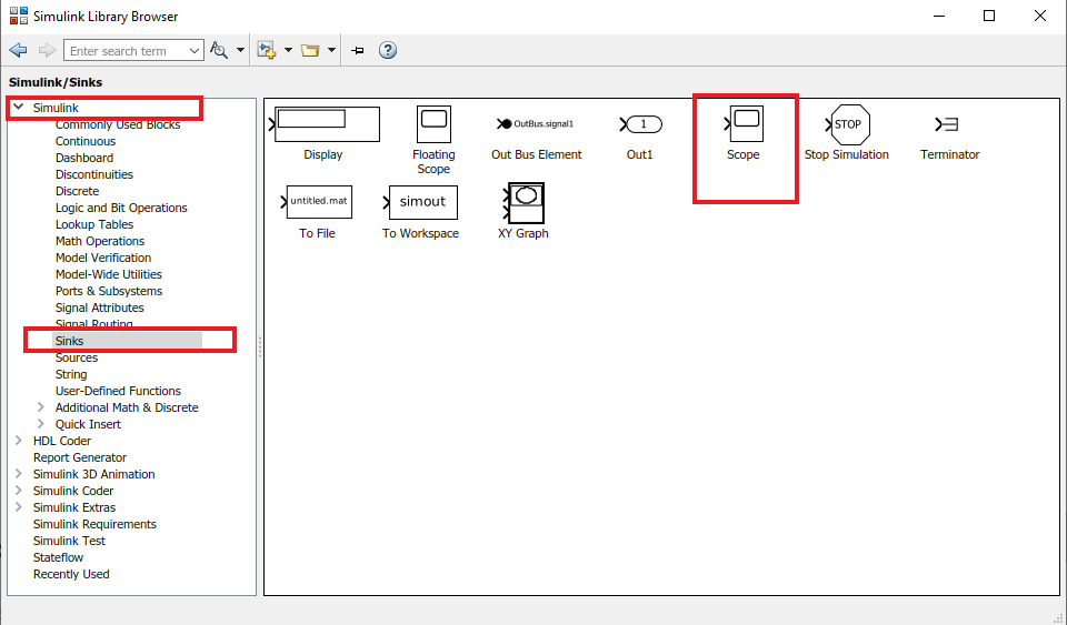
Simulink -> Sinks-> Display
Simulink Library Block – Scope
Simulink -> Sinks-> Scope
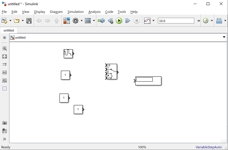
Build The Simulink Model
Now, I have dragged and dropped all the required Simulink Library blocks into my blank Simulink model/canvas.
Now, the first thing, I will do is to configure the multiport switch block. The multiport switch block needs to be configured to mention the number of cases we want to evaluate.
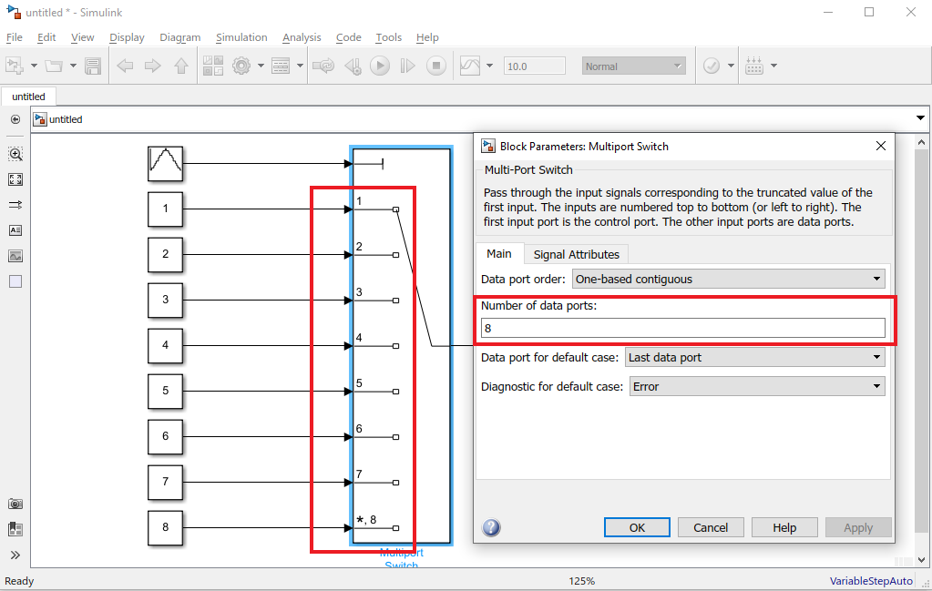
Multiport Switch Block
Now, I will configure the multiport switch block. I can double click on the multiport switch library block. The Block Parameters dialog box will open up, as you can see below. I will mention the number of data port as 8 ( 7 days and default case, as per our example code).
Simulink Model Output-1
The first port in the multiport switch block is for input. First, let’s set the input as 5 and execute the model. As you can see below, the output is displayed as 5, as we expected.

Simulink Model Output-2
Now, I will use the Repeating Sequence Stair Block and see the output w.r.t. time.
First, I will set the input data for the Repeating Sequence Stair block. I will double click on the block and the block parameter setting window will pop up. I have set the input data as – [1 2 3 4 5 6 7 6 5 4 3 2 1]
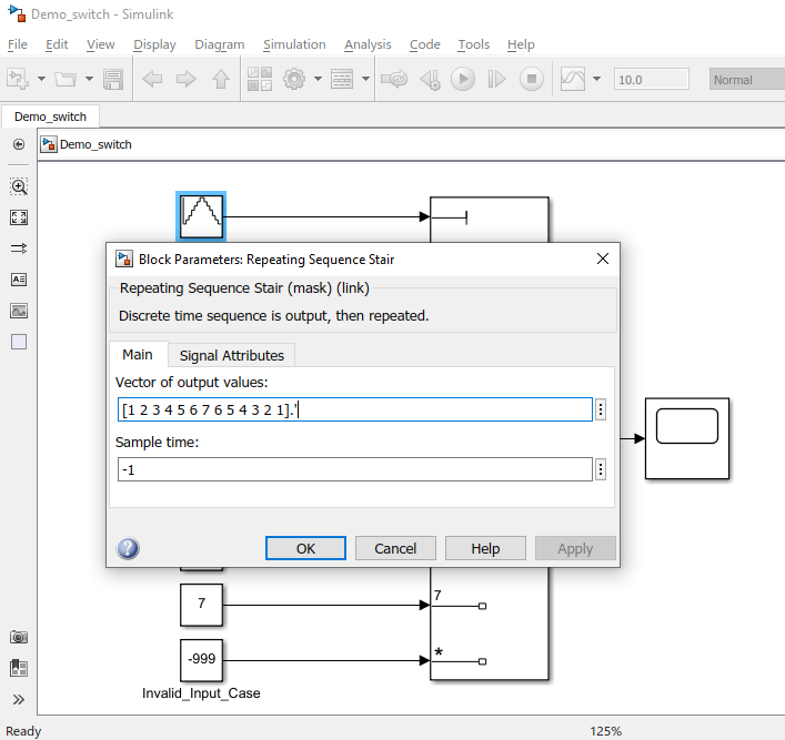
Now, let’s execute the model by clicking the green play button on the top and open the scope block to see the output:

Download Sample Model
You can download the Sample Model by Clicking HERE.
Summary
Matlab/Simulink is a well known and very popular tool used for Model Based Software Development in the aerospace and automotive industry.
Today, in this article (Simulink Tutorial Series – 3), I have explained step-by-step, how to implement switch-case logic in the Simulink model using Simulink library blocks from scratch.
If you have any questions, please feel free to comment in the comment box below. 👇👇👇
I will keep sharing useful real-life Simulink model example here – Simulink Tutorial Series.
Stay Tuned!

This post was published by Admin.
Email: admin@TheCloudStrap.Com