
Simulink Tutorial Series – 2

Are you new to the world of Model-Based Development? Are you looking for a good working Simulink model examples / Simulink Tutorial to understand how Model-Based Development works?
If yes, then you are on the right page!
In this article, I am going to discuss exactly, what you are looking for.
Matlab/Simulink is the leading software in the industry for model based development.
There are several other online resources, where you can get theoretical knowledge about Matlab/Simulink. But, there are not many resources to explain the theory along with good examples. This is going to be a series of articles. This is the second article in this series.
In every series, I will add real-life working examples and show how to build models for a particular problem.
Learning Goal
In this article, I am going to explain you how you can apply the if-else condition in simulink model. If you are familiar with other programming languages such as C, C++, Java or any other programming languages, you already know that every programming language has if-else logic.
In simulink, we can build a model including if-else logic.
So, if you go through this article, you will be able to build your own Simulink model using if-else logic.
Assumption
I am assuming, you already gone through my previous article – Simulink Tutorial – Series I. If not, you can just take a look at HERE.
What We already know
We already know –
- How to start Matlab
- How to open the Simulink from Matlab
- How to open a Blank Simulink Model
- How to open Simulink Library Browser
- How to find a block in Simulink Library Browser
I have discussed all the above points in my previous post.
If-Else Logic
Most of you, who have previous programming background, you already know what a if-else logic does and how it works. However, if you do not know if-else logic, here is what it does:
- The if-else construct evaluates a condition and if the condition outcome is True, the if path executes
- If the condition becomes False, the else path executes
if(rain==1)
{
          printf("It's a rainy day");
}
else
{
         printf("It's a sunny day");
}
So, when the “rain” variable is set to 1, the printf() function under the if condition will execute. When the condition fails, i.e. rain variable is set to 0, the printf() under the else condition executes.
Simulink Blocks needed for if-else logic implementation
I need the following Simulink blocks to implement the if-else logic:
- Constant Block
- Switch Block
- Display block
To be able to show the output, I need a display block. However, this is not needed to implement the core logic of if-else.
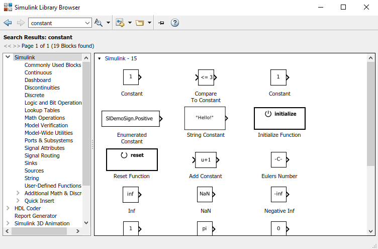
Constant Block
You can open the Simulink Library Browser and search for the constant block. Then drag and drop to the Simulink Blank model.
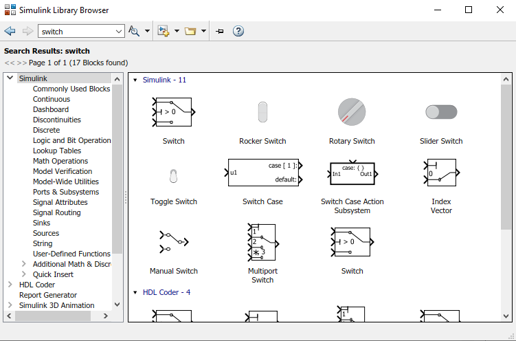
Switch Block
I can open the Simulink Library Browser and search for the switch block. Then drag and drop to the Simulink Blank model.
I can also simply go the Signal Routing section in the Simulink Library Browser window and find the switch block.
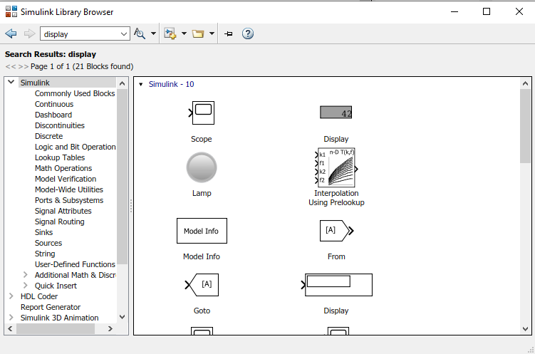
Display Block
Similarly, I can easily find the display block in the Simulink Library Browser by typing the display in the find box.
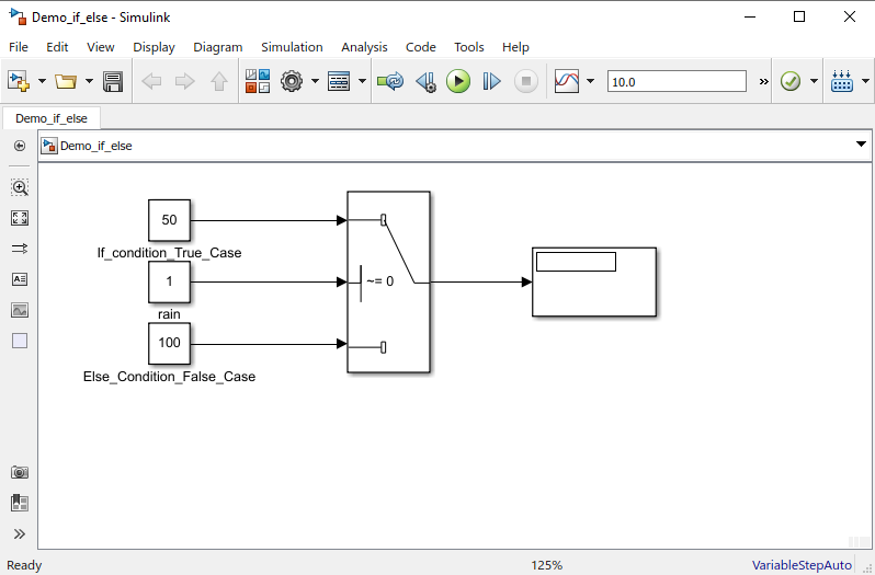
Build the Simulink Model
Now, I need to just drag and drop all the required blocks from the Simulink Library Browser and put in the blank Simulink model.
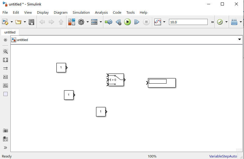
Now, I just need to connect them up correctly to implement the if-else logic.
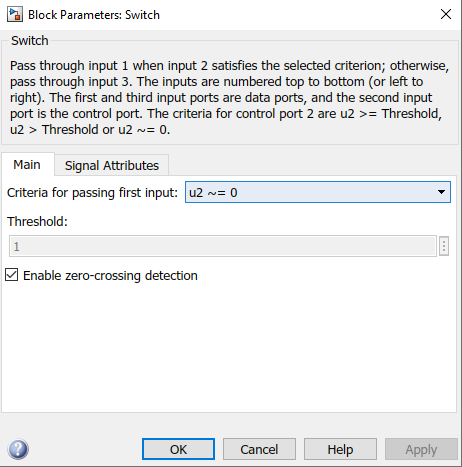
Now, you must be wondering how did I set up the if condition in the switch block. Its’s very easy. Just double-click on the switch block and a dialog box will open up to configure the switch block. As you can see below, you need to set the criteria for passing the first input (u2 ~= 0).
Simulink Model Output
Now, since I have completed building the model, I just now save the model and execute it by hitting the green play button.
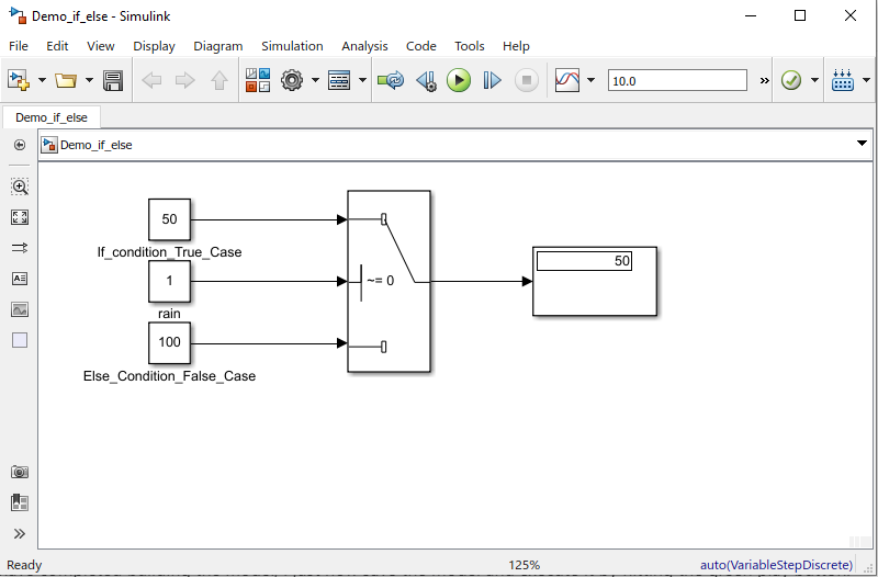
So, I have got the expected output. The switch condition I have set was u2 ~=0. Here the u2 is the denoted as constant block – “rain”. The “rain” is set to 1. Therefore, the condition (u2 ~=0) holds True. That’s why the first input (i.e. 50) becomes the output of the switch block.
Now, I will set the “rain” to 0 and execute the model again and see the output. My expected output in this case, would be 100.
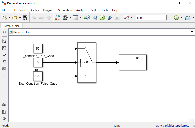
So, I have built a if-else logic in using Simulink Model.
Download Sample Model
You can download the sample Simulink model by Clicking HERE.
Summary
Matlab/Simulink is a well known and very popular tool used for Model Based Software Development in the aerospace and automotive industry.
Today, in this article (Simulink Tutorial Series – II), I have explained step-by-step, how to create a simple Simulink model from scratch.
Just in case you have missed my first post in this series, you can find it here – Simulink Tutorial Series – I.
If you have any questions, please feel free to comment in the comment box below.
I will keep sharing useful real-life Simulink model example here – Simulink Tutorial Series.
Stay Tuned!

This post was published by Admin.
Email: admin@TheCloudStrap.Com