
Simulink Tutorial Series – 10

In this article, I am going to explain you how to design the Limit function in Simulink.
I will build the Simulink models for Limit function step-by-step.
Matlab/Simulink is the leading software for model based development in aerospace, automotive industry etc.
There are several other online resources, where you can get theoretical knowledge about Matlab/Simulink. In fact, Matlab has very good documentation for each of their products. But, there are not many resources to explain the theory along with good working examples. This is going to be a series of articles. This is the 10th article in this series.
In every article in this Simulink Tutorial Series, I will add real-life working examples and show how to build models for a particular problem.
Problem Statement
Here is the Problem statement –
Design the Limit function in Simulink so that –
1. The Output is equal to the Input value when the input value is in between Low and High
2. The Output is set to Low value, when the input is lower than Low
3. The Output is set to High value, when the input is higher than High
Note: This is also a popular interview question for Matlab/Simulink.
Assumption
I am assuming, you have already gone through my previous articles.
In one of these articles, I have explained the delay block in Simulink Library. Understanding the delay block is crucial to implement the up down counter in Simulink.
Design the Limit function in Simulink
To design the Limit function, I need the following Library Blocks:
- Switch block
- Relational Operator Block
- Constant block
- Display block
If you have gone through my previous posts, you already know how to find these blocks in the Simulink Library Browser.
Now, I will just get these blocks from the Simulink Library browser and put them in a blank Simulink model/canvas.
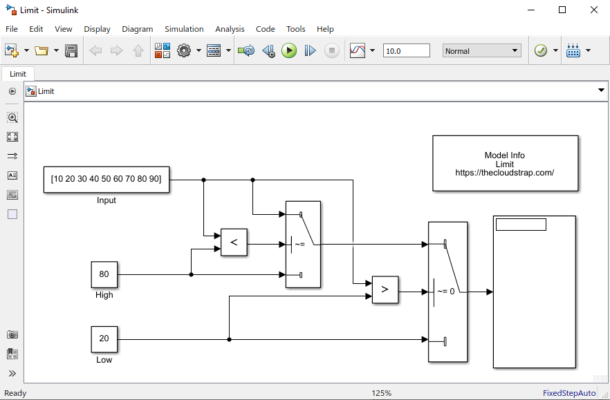
I will join them up accordingly to implement the Limit function. As you can see below, I have used to relational operator blocks. One is to check if the input value is beyond the High value. Another is used to check if the input value is lower than the Low value. The output of the relational blocks goes as a control input for the respective switch blocks.
If the output of the relational operator block is True, the switch block will pass on the first input as an output. If it is False, the switch block will pass on the third input as an output.
The second input of the switch block act as a control input.
Model Output
Now, I will execute the model by hitting the green play button.
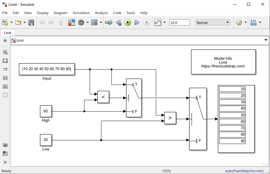
As you can see below, the output is limited to the range – <20 to 80>. The input vector is = [10 20 30 40 50 60 70 80 90].
The High value is 80 and the Low value is 20. So, if the input value is higher than or equal to High value, it will output High value. If the input value is lower than or equal to Low value, it will output Low value.
In this case, if you see the first input i.e. 10 is lower than the Low value i.e. 20. Therefore, the output is limited and set to 20. Similarly, the last input element of the vector is 90 which is higher than the High value i.e. 80. Therefore, the output is limited and set to 80.
Download Sample Model
You can download the Sample Model by Clicking HERE.
Summary
Matlab/Simulink is a well known and very popular tool used for Model Based Software Development in the aerospace and automotive industry.
Today, in this article(Simulink Tutorial Series – 10), I have explained step-by-step, how to implement the Limit function in the Simulink model using Simulink library blocks from scratch.
If you have any questions, please feel free to comment in the comment box below. 👇👇👇
I will keep sharing useful real-life Simulink model example here.
Happy learning!

This post was published by Admin.
Email: admin@TheCloudStrap.Com