
Simulink Tutorial Series – 9

In this article, I am going to explain to you how to calculate Min and Max in Simulink using the Simulink library block as well as the user-defined model.
I will build the Simulink models for Min/Max step-by-step.
Matlab/Simulink is the leading software for model based development in the aerospace, automotive industry etc.
There are several other online resources, where you can get theoretical knowledge about Matlab/Simulink. In fact, Matlab has very good documentation for each of their products. But, there are not enough resources to explain the theory along with good practical examples. This is going to be a series of articles. This is the 9th article in this series.
In every article in this Simulink Tutorial Series, I will add real-life working examples and show how to build models for a particular problem step-by-step.
Problem Statements
Here is the Problem statements –
Calculate Min value in a given vector using the Simulink Library block.
Calculate Max value in a given vector using the Simulink Library block.
Calculate Min value using Simulink
Calculating the minimum value using the Simulink Library block is very easy – you just need to use the Min block. You can find the min block in the Simulink Library Browser.
So, to demonstrate an example for calculating Min value using Simulink, I need the following Simulink Library Blocks:
- Min block
- Constant block
- Display block
If you have gone through my previous posts, you already know how to find these blocks in the Simulink Library Browser.
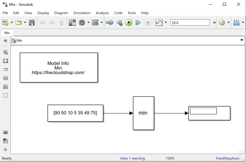
Now, I will just need to get these library blocks from the Simulink Library browser and drag and drop them in a blank Simulink model/canvas. I will then join them appropriately.
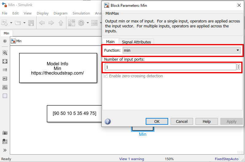
You need to double click on the Min block and ensure the following configuration in the “Block Parameters: Min” window, as shown below.
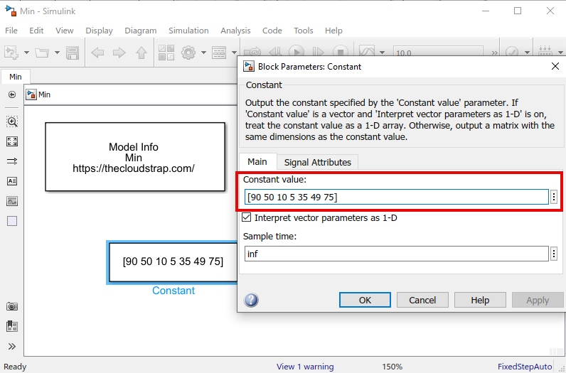
The constant block is used as an input to the Min block. I will double click on the constant block to open the block parameters window and set the input as a vector – [90 50 10 5 35 49 75]. The minimum value of this vector is 5. In the next step, I will execute the model.
Model Output
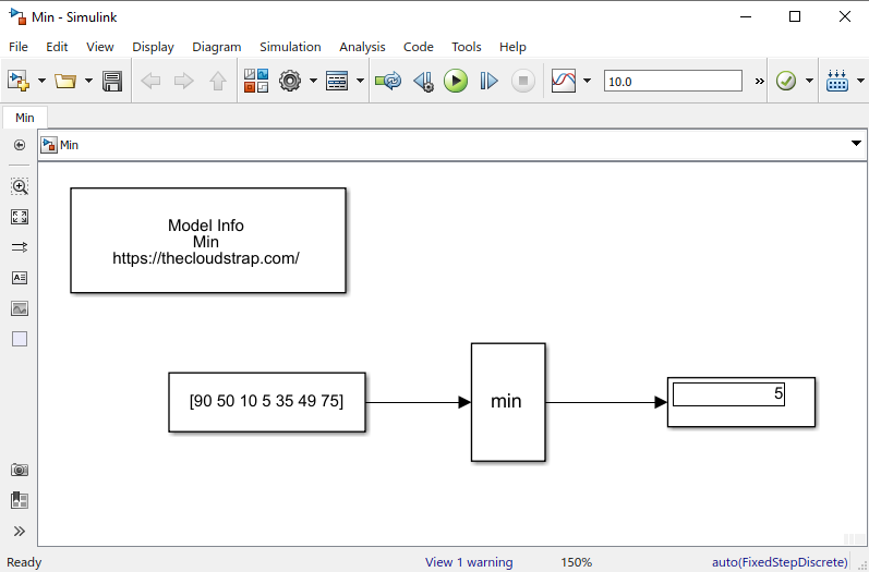
Now, I will execute the model by hitting the green play button. As you can see below, the output is 5, as expected based on the input vector.
Here, the Min block receives one input vector ([90 50 10 5 35 49 75]) and then calculates the minimum value of the input vector. The output of the min block is then displayed on the display block.
You can mention as many elements as you want in the input vector by just modifying the constant block properties. You can also have multiple input ports instead of one input vector.
Calculate Max value using Simulink
Now, let’s design our own model to calculate the maximum value from a given input vector in Simulink.
So, to demonstrate an example for calculating maximum value using Simulink, I need the following Simulink Library Blocks:
- Max block
- Constant block
- Display block
Now, I will just need to get these library blocks from the Simulink Library browser and drag and drop them in a blank Simulink model/canvas. I will then join them appropriately.
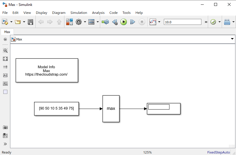
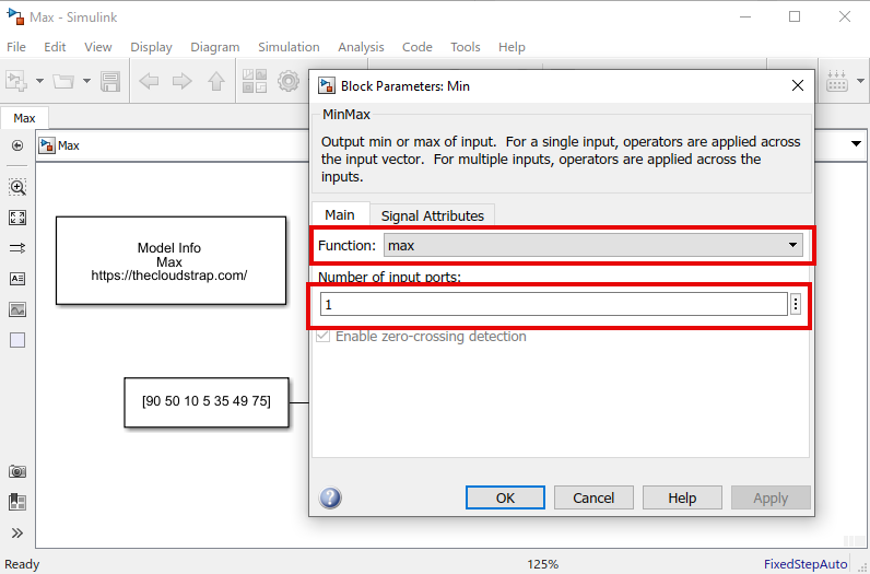
You need to double click on the Max block and ensure the following configuration in the “Block Parameters: Max” window, as shown below. make sure that the number of input port is set to 1.
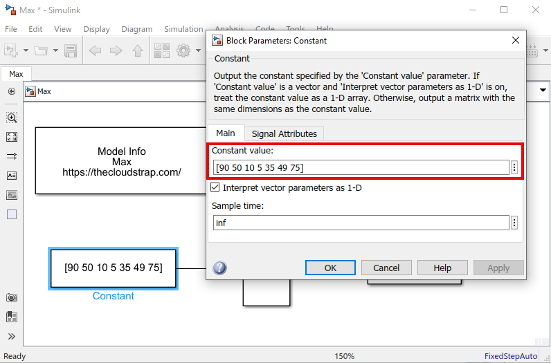
The constant block is used as an input to the Max block. I will double click on the constant block to open the block parameters window and set the input vector as – [90 50 10 5 35 49 75]. The maximum value of this vector is 90. In the next step, I will execute the model.
Model Output
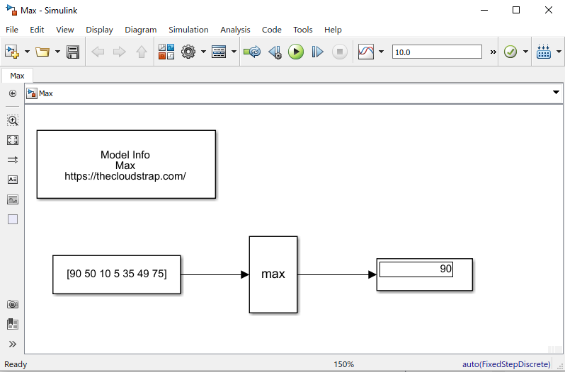
Now, I will execute the model by hitting the green play button. As you can see below, the output is 90, as expected based on the input vector.
Here, the Max block receives one input vector ([90 50 10 5 35 49 75]) and then calculates the maximum value of the input vector. The output of the min block is then displayed on the display block.
You can mention as many elements as you want in the input vector by just modifying the constant block properties. You can also have multiple input ports instead of one input vector.
Download Sample Model
You can download the Sample Model by Clicking HERE.
Summary
Matlab/Simulink is a well known and very popular tool used for Model Based Software Development in the aerospace and automotive industry.
Today, in this article (Simulink Tutorial Series – 9), I have explained step-by-step, how to calculate the Min/Max of a given input vector in the Simulink model using Simulink library blocks from scratch.
If you have any questions, please feel free to comment in the comment box below. 👇👇👇
I will keep sharing useful real-life Simulink model example here – Simulink Tutorial Series.
Happy learning!

This post was published by Admin.
Email: admin@TheCloudStrap.Com