
Simulink Tutorial Series – 7

In this article, I am going to explain you how to design up down counter in Simulink.
I will build the Simulink models for the up down counter step-by-step.
Matlab/Simulink is the leading software for model based development in aerospace, automotive industry etc.
There are several other online resources, where you can get theoretical knowledge about Matlab/Simulink. In fact, Matlab has very good documentation for each of their products. But, there are not many resources to explain the theory along with good working examples. This is going to be a series of articles. This is the 7th article in this series.
In every article in this Simulink Tutorial Series, I will add real-life working examples and show how to build models for a particular problem.
Problem Statement
Here is the Problem statement –
Design Up Down Counter using Simulink.
Note: This is also a common interview question for Matlab/Simulink.
Assumption
I am assuming, you have already gone through my previous articles –
Simulink Tutorial Series – 1
Simulink Tutorial Series – 2
Simulink Tutorial Series – 3
Simulink Tutorial Series – 4
Simulink Tutorial Series – 5
Simulink Tutorial Series – 6
In one of these articles, I have explained about the delay block in Simulink Library. Understanding the delay block is crucial to implement the up down counter is Simulink.
Design Up Counter in Simulink
First of all, I need the following Simulink Library blocks to design up down counter in Simulink and showcase a functionality:
- Add block
- Delay block
- Constant block
- Display block
- Scope block
If you have already gone through my previous articles, you already know how to find these library blocks in Simulink Library Browser and get them in a blank Simulink model.

Now, I will join these blocks appropriately as shown in the below example:
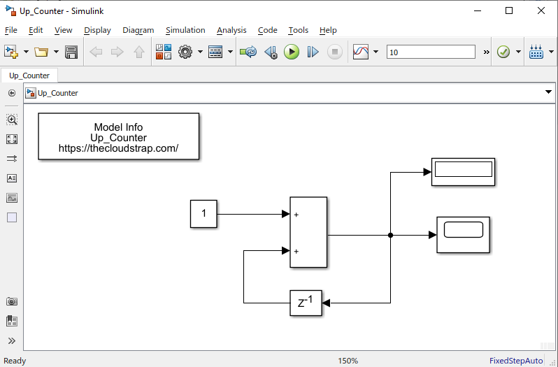
Model Output
Now, since my model is ready, I will execute the model by hitting the green play button. Let’s see if we can get the right output.

Now, you can double click on the scope block and the scope window would open up. This is the graph of the output signal. I had set the simulation time as 10. The up counter model increased by one in every sample step.

However, we can improve the above model by just changing the Configuration parameters.
Solver Type = Fixed Step
Fixed-Step-Size = 1
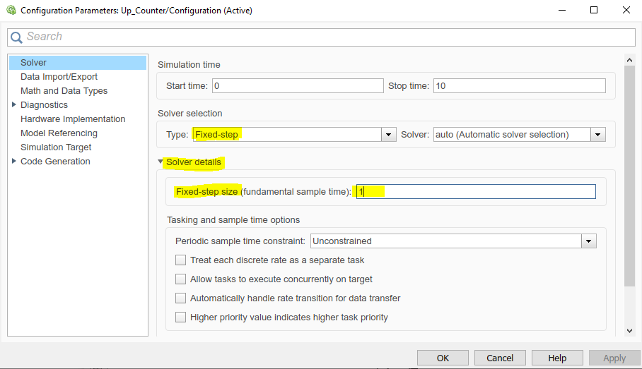
Now, save the model and execute it again. Then, double click on the scope block. You should be able to see the output graph as shown in the below window. The step size is matched with the sample time which is 1.
But, still as you can see below the initial step starts from 1 and not from zero. So, I need to tweak the model.

I will add a delay block before the add block as shown below. This will delay the input by one cycle and we will get out desired result.
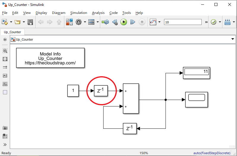
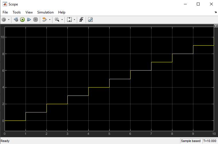
Now, again execute our model and see the scope output. As you can see below, now we are getting the right output – the initial output starts from zero, and the step size matches with the sample time.
So, we have successfully designed a up counter in Simulink.
Design Down Counter in Simulink
To design the down counter, I need the following Simulink Library blocks:
- Add block
- Delay block
- Constant block
- Display block
- Scope block
If you have already gone through my previous articles, you already know how to find these library blocks in Simulink Library Browser and get them in a blank Simulink model.
I will just drag and drop the required library blocks in a blank Simulink model and join them up appropriately as shown below:

Model Output
Now, let me execute the model by hitting the green play button. The simulation time is set as 10.0. This is the default simulation time.
You can increase it to 20.0 or 30.0 based on your requirement.
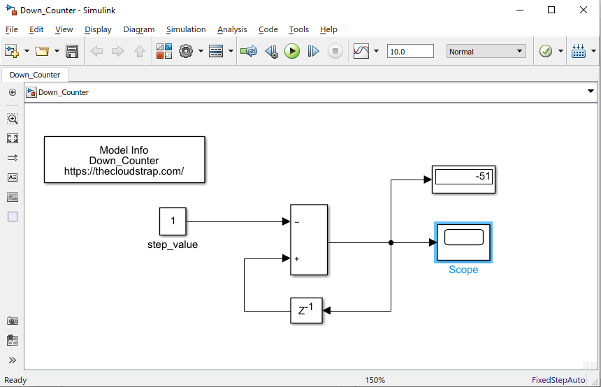
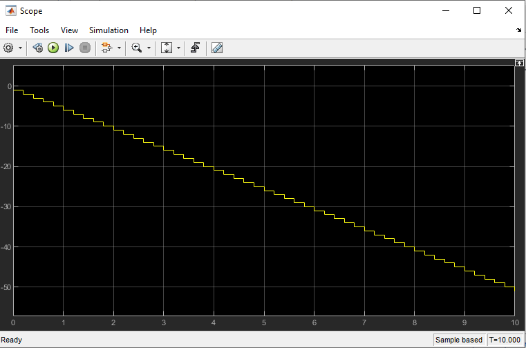
As you can see the output is -51. You can now double click on the scope block and the scope window would open up. This is the graph of the output signal. I had set the simulation time as 10. The down counter model decreased by one in every sample step.
However, you can improve the above model by just changing the Configuration parameters as you have done in case of up counter.
Solver Type = Fixed Step
Fixed-Step-Size = 1
Now, you can save the model and execute it again by hitting the green play button. Then, double click on the scope block. You should be able to see the output graph as shown in the below window. The step size is matched with the sample time which is 1.
But, still as you can see below the initial step starts from 1 and not from zero. So, I need to tweak the model.

I will add a delay block before the add block as shown below. This will delay the input by one cycle and we will get out desired result.
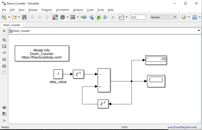
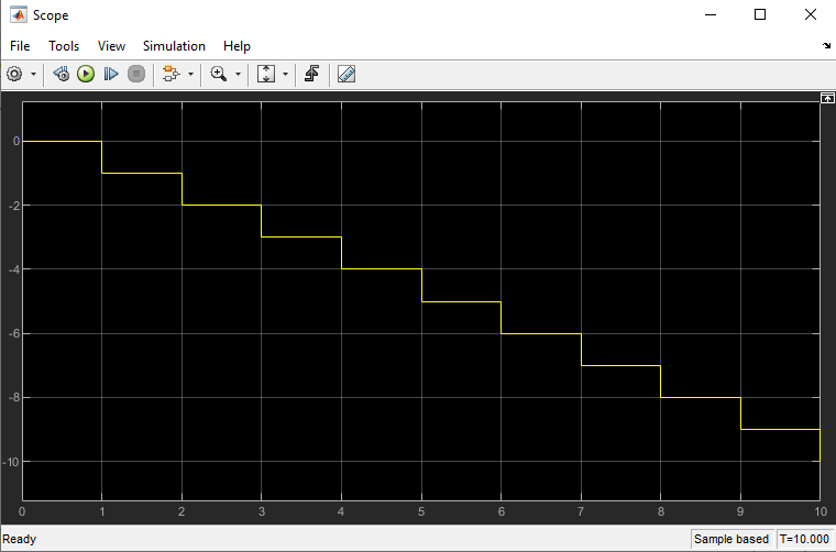
Now, again I have to execute the model. As you can see below, now I am getting the right output – the initial output starts with zero, and the step size matches with the sample time. That means, in every step the down counter is decremented by 1.
So, we have successfully designed a down counter in Simulink.
Download Sample Model
You can download the Sample Model by Clicking HERE.
Summary
Matlab/Simulink is a well known and very popular tool used for Model Based Software Development in the aerospace and automotive industry.
Today, in this article (Simulink Tutorial Series – 7), I have explained step-by-step, how to design up down counter in the Simulink model using Simulink library blocks from scratch.
If you have any questions, please feel free to comment in the comment box below. 👇👇👇
I will keep sharing exciting real-life Simulink model examples here – Simulink Tutorial Series.
Happy learning!

This post was published by Admin.
Email: admin@TheCloudStrap.Com